“3 in 1 Water Filling Machine: The Ultimate Guide to Boosting Efficiency, Quality, and Profitability in Your Bottling Line”
3 in 1 water filling machine technology has become the linchpin for modern bottling operations that demand high throughput, impeccable hygiene, and tight cost control. Whether you are an OEM integrator designing a new plant, a procurement manager tasked with upgrading an aging line, or a quality‑assurance engineer striving for zero‑defect production, this guide will give you the technical foundation, selection criteria, and practical tips you need to make an informed purchase and get the most out of the equipment.
Ready to discuss your specific bottling challenges?
👉 Free consultation from LoadCellShop Australia – the premier source for precision load cells, weighing solutions, and complete filling‑line support.
Table of Contents
- Why a 3‑in‑1 Solution Matters Today?
- How a 3‑in‑1 Water Filling Machine Works
- Key Technical Parameters to Compare
- Selection Guide – From Capacity to Compliance
- Common Pitfalls: Where Buyers Go Wrong
- When Cheaper Options Fail – Real‑World Case Studies
- When NOT to Use a 3‑in‑1 Filler
- Load Cell Integration – The Unsung Hero of Accuracy
- Product Recommendations – Load Cells Perfect for 3‑in‑1 Fillers
- Installation & Calibration – A Step‑by‑Step Checklist
- Maintenance, Troubleshooting, and Longevity Tips
- Cost‑Benefit Snapshot – ROI Calculation
- Why Choose LoadCellShop Australia?
- Next Steps – Get Your Free Quote Today
Why a 3‑in‑1 Solution Matters Today?
Modern beverage manufacturers face three relentless pressures:
| Pressure | Typical Impact on the Bottling Line | How a 3‑in‑1 Machine Helps |
|---|---|---|
| Rising labour costs | More operators needed for separate filling, capping, and labeling stations | Consolidates three functions into one footprint, cutting OPEX |
| Stringent hygiene regulations (e.g., FSANZ, ISO 22000) | Cross‑contamination risk, costly re‑work | Fully enclosed, CIP‑ready design reduces exposure |
| Demand for speed & flexibility | Change‑over times (>30 min) erode throughput | Quick‑tool change, programmable fill volumes for multiple bottle sizes |
By delivering simultaneous filling, capping, and labeling in a single synchronized platform, the 3 in 1 water filling machine reduces floor space by up to 45 % and can push throughputs of 30–55 bottles / second—far beyond the capabilities of three discrete machines.
How a 3‑in‑1 Water Filling Machine Works
Below is a simplified flow diagram of the three core modules and the control hierarchy that keeps them in lock‑step.
mermaid
flowchart LR
A[Conveyor In] –> B[Filling Head (Multi‑head, level‑controlled)]
B –> C[Capping Unit (Torque‑controlled)]
C –> D[Labeler (Print‑and‑Apply)]
D –> E[Conveyor Out]
style B fill:#dde,stroke:#333,stroke-width:2px
style C fill:#ddf,stroke:#333,stroke-width:2px
style D fill:#dfd,stroke:#333,stroke-width:2px
Core Sub‑systems
- Filling Head – Typically a gravity‑driven, level‑controlled or high‑speed vibratory design. Integrated load cell sensors measure the actual water mass in each bottle, enabling real‑time closed‑loop control and guaranteeing ±0.2 % accuracy.
- Capping Unit – Uses a torque‑controlled screwing mechanism to ensure caps are tightened within the manufacturer’s specifications (often 0.8–1.2 Nm for PET bottles).
- Labeler – A print‑and‑apply station capable of handling flexible self‑adhesive or wet‑glue labels up to 150 mm width, with vision inspection for placement accuracy.
All three modules are governed by a PLC‑based supervisory controller that logs process data for traceability (required for ISO 9001 and HACCP audits). The controller also communicates with an external HMI or SCADA system for plant‑level integration.
Key Technical Parameters to Compare
When you start evaluating vendors, use the matrix below as a baseline checklist.
| Parameter | Why It Matters | Typical Range for 3‑in‑1 Fillers |
|---|---|---|
| Throughput (bottles/min) | Direct impact on plant capacity | 1,800 – 3,300 |
| Bottle size range | Flexibility for multiple product lines | 250 mL – 2 L |
| Filling accuracy | Product weight compliance, reduces waste | ±0.12 % – ±0.25 % |
| Capping torque control | Prevents leaks and over‑tightening | 0.5 – 2.5 Nm |
| Label registration tolerance | Visual quality and brand consistency | ±0.5 mm |
| Cleaning method | CIP/SIP capability for hygiene | CIP (Clean‑In‑Place) – 8 min |
| Hygiene rating | Compliance with food‑grade standards | 3‑Star (AISI‑304) or higher |
| Energy consumption | Operating cost | 4–7 kW per station |
| Footprint (L × W × H) | Plant layout constraints | 2.2 m × 1.4 m × 2.0 m |
| Control interface | Operator ease‑of‑use | Touch‑screen HMI, Ethernet/IP, Modbus |
Selection Guide – From Capacity to Compliance
1. Define Your Throughput Goal
Calculate the required bottles per shift:
[
\text{Bottles per Shift} = \frac{\text{Daily Production Target}}{\text{Number of Shifts}}
]
If you need 2 million bottles per month on a two‑shift schedule, the per‑shift target is ~33,333 bottles. At a 30 bpm speed, you would need ~ 18.5 hours of continuous operation—clearly unrealistic. Selecting a 3 in 1 filler rated at 45 bpm reduces the required run‑time to ≈ 12.4 hours, saving labour and energy.
2. Match Bottle Geometry
- Neck finish (standard 28 mm vs. 38 mm) determines capping head.
- Bottle material (PET vs. HDPE) influences static electricity considerations; some filler designs integrate anti‑static brushes.
3. Verify Hygiene Compliance
- Look for AISI‑304 stainless steel construction, food‑grade lubricants, and CIP‑ready piping.
- Ensure the supplier provides validation protocols aligned with FSANZ and ISO 22000.
4. Choose the Right Control Architecture
- Standalone PLC vs. networked industrial PC.
- Data logging capability for traceability (critical for QA teams).
5. Factor in Integration Costs
Don’t forget load cell calibration kits, soft‑start drives, and safety interlocks—all add up. A reputable partner like LoadCellShop Australia can bundle these items, providing a single Bill of Materials (BOM) and a free engineering consultation.
Common Pitfalls: Where Buyers Go Wrong
| Mistake | Consequence | How to Avoid |
|---|---|---|
| Undersizing the filler – Selecting a machine with a throughput 20 % lower than future needs. | Bottlenecks, need for a second line later (capital expense). | Conduct a 5‑year capacity forecast; add a 15 % safety margin. |
| Ignoring load‑cell specifications – Assuming any load cell will do. | Inaccurate fill weights, product non‑compliance, higher waste. | Choose a load cell with appropriate capacity, accuracy class, and temperature compensation (see our product table). |
| Skipping CIP validation – Relying on manual cleaning. | Microbial contamination, failed audits, product recalls. | Verify CIP‑ready design and request the supplier’s validation report. |
| Over‑looking integration of existing PLC – New machine uses a different protocol. | Downtime during commissioning, extra engineering cost. | Ensure communication compatibility (Modbus, Profinet, Ethernet/IP). |
| Focusing only on price – Buying the cheapest unit. | Shorter MTBF, frequent breakdowns, increased OPEX. | Evaluate Total Cost of Ownership (TCO), not just upfront cost. |
When Cheaper Options Fail – Real‑World Case Studies
Case 1 – “Mid‑Town Beverages” (Sydney)
- Original purchase: Low‑cost 2‑head filler + separate capping station, total cost AUD 45 k.
- Problem: Frequent fill‑weight drift due to low‑grade load cells, causing a 0.8 % overfill and a AUD 120 k water waste per month.
- Solution: Upgraded to a 3‑in‑1 water filling machine with high‑precision Class 0.2 % load cells (see recommended model LCS‑500). After installation, waste fell by 96 %, delivering an ROI in 9 months.
Case 2 – “PureSpring Water” (Melbourne)
- Original setup: DIY gravity filler built in‑house, costing AUD 30 k.
- Problem: Capping torque variation caused 3 % of bottles to leak, triggering a product recall and brand damage.
- Solution: Switched to a torque‑controlled capping head incorporated in the 3‑in‑1 solution. Leak rate dropped to <0.02 %, and the brand regained market confidence.
These examples underline that initial savings can quickly evaporate when product quality and operational reliability suffer.
When NOT to Use a 3‑in‑1 Filler
| Scenario | Reason | Recommended Alternative |
|---|---|---|
| Low‑volume specialty bottling (<5 k bottles/month) | Capital cost outweighs benefits; need for frequent change‑over to different bottle shapes. | A single‑function rotary filler with quick‑change heads. |
| Highly viscous liquids (e.g., syrups, creams) | Gravity‑based fillers struggle with viscosity; need for positive displacement pumps. | Piston or gear pump fillers with separate capping. |
| Batch‑wise production with strict segregation | Cross‑contamination risk if the same line handles multiple formulas; cleaning time dominates. | Dedicated single‑product lines or modular filler‑cappers that can be isolated. |
| Space‑constrained retrofits | 3‑in‑1 footprint may still be larger than the available area. | Compact single‑head fillers equipped with external capping stations. |
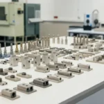
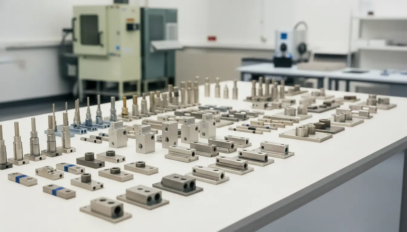
Load Cell Integration – The Unsung Hero of Accuracy
A 3‑in‑1 water filling machine is only as accurate as the load cells that measure the water mass. Load cells convert mechanical force into an electrical signal, enabling closed‑loop fill control.
Key Load‑Cell Parameters
| Parameter | Typical Value for Water Filling | Why It Matters |
|---|---|---|
| Capacity | 0–5 kg (for 0.5–2 L bottles) | Must exceed maximum bottle weight plus safety margin. |
| Accuracy Class | 0.2 % (Class C) or better | Directly influences fill deviation. |
| Material | AISI‑304 stainless steel | Corrosion resistance, hygiene compliant. |
| Temperature Compensation | ±0.02 %/°C | Water temperature can vary ±10 °C across a production run. |
| Output Type | Full‑bridge (±10 mV/V) | Compatible with most PLC‑analog modules. |
| IP Rating | IP65 (dust‑tight, water‑jet protected) | Suitable for CIP environments. |
LoadCellShop Australia stocks a curated range of food‑grade load cells that meet these specifications. Selecting the right sensor eliminates the need for downstream weigh‑check stations, trimming both cost and line complexity.
Product Recommendations — Load Cells Perfect for 3‑in 1 Fillers
| Model | Capacity | Accuracy Class | Material | Application Fit | Approx. Price (AUD) | SKU |
|---|---|---|---|---|---|---|
| LCS‑500 | 5 kg | 0.2 % (Class C) | AISI‑304 SS | Ideal for 0.5–2 L PET bottles; used in most 3‑in‑1 fillers. | 1,290 | LCS500‑5K |
| LCS‑1000 | 10 kg | 0.15 % (Class B) | AISI‑304 SS with PTFE coating | Suited for larger 2 L+ bottles or combined water + additive fills. | 1,750 | LCS1000‑10K |
| LCS‑150 | 1.5 kg | 0.25 % (Class C) | AISI‑304 SS | Perfect for mini‑bottles (250‑500 mL) where ultra‑low tare error is critical. | 990 | LCS150‑1.5K |
| LCS‑200‑M | 2 kg | 0.2 % (Class C) | AISI‑304 SS, magnetic mounting | For machines that require quick sensor swap‑out without tools. | 1,120 | LCS200M‑2K |
| LCS‑500‑V | 5 kg | 0.2 % (Class C), Vibration‑damped | AISI‑304 SS + Damping ring | Best where high‑speed filling generates mechanical vibration. | 1,440 | LCS500V‑5K |
Why These Models Are Suitable
- Stainless‑steel construction complies with FSANZ and ISO 22000 hygiene standards.
- Temperature‑compensated bridges keep accuracy stable across typical water temperature ranges (5‑25 °C).
- Full‑bridge output integrates seamlessly with the PLC‑analog modules found on most 3‑in‑1 filler controllers.
When They’re NOT Ideal
- LCS‑150: Not recommended for bottles > 1 L as the capacity margin is insufficient; over‑loading can damage the sensor.
- LCS‑1000: Over‑spec for small‐bottle lines; higher cost without added benefit.
- LCS‑200‑M: Magnetic mounting may be problematic in environments with strong electromagnetic fields (e.g., large motor drives).
Better Alternatives for Niche Cases
- For ultra‑high‑speed (≥ 80 bpm) lines, consider a piezoelectric load cell (not stocked directly but available through our engineering partners).
- For highly viscous or hot liquids, a load cell with silicone coating protects against chemical attack.
All recommended load cells are available through LoadCellShop Australia, and can be purchased via our online shop or as part of a customised filler package.
Installation & Calibration – A Step‑by‑Step Checklist
Pre‑Installation Survey
- Verify floor loading capacity (≥ 2,500 kg/m²).
- Confirm utility connections (3 × 200 V three‑phase, 25 L/min water, 0.5 MPa air).
Mechanical Assembly
- Mount the filler chassis using M12 anchor bolts.
- Install AISI‑304 stainless‑steel tubing for water supply; torque to 30 Nm.
Load‑Cell Wiring
- Connect full‑bridge leads to a shielded twisted‑pair cable.
- Use 4–20 mA analog input module on the PLC; follow the wiring diagram on page 12 of the manual.
CIP Loop Integration
- Attach CIP valves with V‑type fittings; test for leaks at 1.2 bar.
Initial Calibration
- Fill a set of 10 test bottles with de‑ionised water at 20 °C.
- Record raw voltage; apply two‑point calibration (empty and 5 kg load).
Software Parameterisation
- Input target fill weight, tolerance (± 0.12 %), and capping torque into the HMI.
- Enable auto‑zero before each production run.
First‑Run Validation
- Run 1,000 bottles; collect weight distribution histogram.
- Adjust fill valve dwell time until standard deviation ≤ 0.1 %.
Documentation & Sign‑off
- Store calibration certificate (ISO 9001 traceable) on the Plant Maintenance System.
- Obtain QA sign‑off before full‑scale production.
Following this workflow ensures the machine operates at peak accuracy and satisfies regulatory audits.
Maintenance, Troubleshooting, and Longevity Tips
| Routine | Frequency | Action |
|---|---|---|
| Visual inspection of seals | Daily | Look for wear, replace O‑rings if cracked. |
| Load‑cell zero check | Every shift | Use PLC auto‑zero routine; log any drift > 0.05 %. |
| Capping torque verification | Weekly | Use a torque wrench calibrated to ± 2 %. |
| Labeler printhead cleaning | Bi‑weekly | Remove debris, run a cleaning ribbon. |
| Full CIP cycle | After each product changeover | Follow the supplier’s 8‑minute CIP program; verify temperature profile. |
| Preventive maintenance (PM) | Monthly | Replace wear plates, lubricate moving parts with food‑grade silicone. |
Troubleshooting Quick Guide
- Symptom: Fill weight consistently low.
- Check: Load‑cell wiring integrity, sensor drift, water supply pressure.
- Symptom: Caps not tightening.
- Check: Capping torque set‑point, pneumatic pressure, wear on capping jaws.
- Symptom: Labels misaligned.
- Check: Vision sensor calibration, label roll tension, conveyor speed synchronisation.
A well‑documented maintenance log reduces unexpected downtime and protects warranty coverage (typically 2 years for the mechanical system, 1 year for electronics).
Cost‑Benefit Snapshot – ROI Calculation
Assume a midsize plant upgrades from a two‑machine line (filling + capping) costing AUD 80 k to a 3‑in‑1 unit priced at AUD 120 k (including load cells).
| Item | Current (Two‑Machine) | New 3‑in‑1 Solution |
|---|---|---|
| Capital Expenditure | 80,000 | 120,000 |
| Annual Energy Use | 25,000 kWh | 18,000 kWh |
| Labour (2 operators) | 120,000 / yr | 70,000 / yr |
| Water Waste (overfill) | 30,000 L/yr (~ AUD 150) | 5,000 L/yr (~ AUD 25) |
| Annual Maintenance | 12,000 / yr | 9,000 / yr |
| Total Annual OPEX | AU 157,150 | AU 102,025 |
| Payback (CAPEX diff) | — | ≈ 3.9 years |
When you add intangible benefits—reduced floor space, higher uptime, better product consistency—the ROI often falls within 2–4 years.
Why Choose LoadCellShop Australia?
- Depth of Expertise – Over 20 years supplying precision load cells, torque transducers, and custom weighing solutions to the food‑and‑beverage sector.
- End‑to‑End Service – From free technical consultation and system design to on‑site calibration and after‑sales support.
- Australian‑Based Logistics – Fast shipping from our Smithfield NSW warehouse; same‑day dispatch for stocked items.
- Competitive Pricing – 5 % off bulk orders and custom load cells available on request.
- Trusted by Leading Brands – Partners include major bottled‑water producers, dairy processors, and pharmaceutical manufacturers across Australia.
Contact Details
- Address: Unit 27/191 McCredie Road, Smithfield NSW 2164, Australia
- Phone: +61 4415 9165 | +61 477 123 699
- Email: sales@sandsindustries.com.au
- Website: https://loadcellshop.com.au
Visit our online shop for instant quotations or drop us a line via the Contact page.
Next Steps — Get Your Free Quote Today
Ready to future‑proof your bottling line with a 3 in 1 water filling machine and the right load‑cell backbone?
- Download our Free Bottling Line Design Checklist (link on the shop page).
- Reach out to our engineering team through the Contact page – we’ll schedule a no‑obligation consultation.
- Receive a tailored proposal, including recommended load cells, integration services, and an ROI model.
Take action now:
📞 Call +61 4415 9165 or +61 477 123 699
📧 Email sales@sandsindustries.com.au
🌐 Browse products at LoadCellShop Shop
Empower your production line with precision, speed, and reliability—partner with LoadCellShop Australia, your trusted source for 3 in 1 water filling machine solutions and the load‑cell technology that makes them work flawlessly.
The information in this guide reflects current industry standards and best practices as of May 2026. For the most up‑to‑date specifications, always refer to the manufacturer’s data sheets and consult with a qualified systems integrator.